
Cisco 2960 switch and SPAN vs RSPAN
July 3, 2016
Last week, I had the opportunity to work with some Gigabit PoE Cisco 2960 switches, an Avaya IP Office VoIP system,
and a Layer 2–based Ethernet recording system. The recording system had two dedicated Ethernet ports designed to receive mirrored traffic from the VoIP
VLAN—what I came to call the “tap” interfaces.
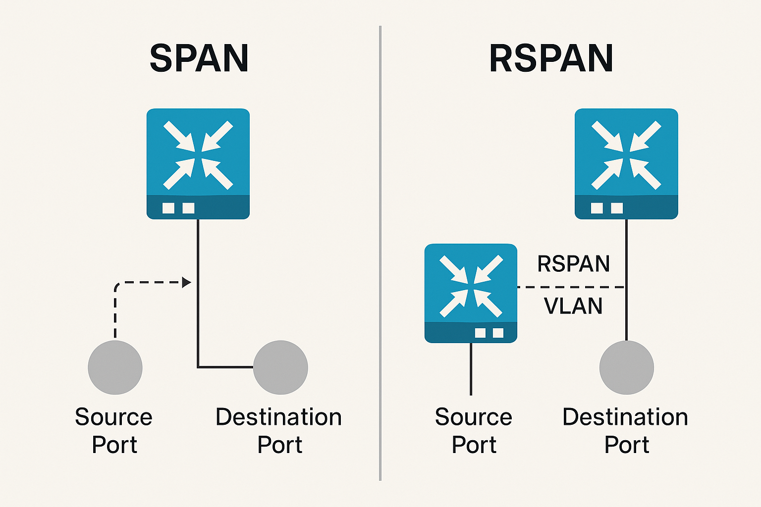
After reviewing the 2960 specifications, I found two features: SPAN and RSPAN. This was my first time working with them, and it took a bit of reading to realize that RSPAN is used to capture traffic from remote switches, whereas SPAN is for capturing or mirroring traffic from the local switch. However, the two cannot be mixed—you cannot send both RSPAN and local SPAN traffic to the same destination port.
In my case, there were only two switches, but VoIP phones could be connected to any port on either switch and assigned to VLAN 12 via LLDP. Both tap ports were connected to the primary server room switch—in this case, let’s say “Gi1/0/2” and “Gi1/0/3.” The “Gi1/0/1” interface was used as the uplink port on both switches.
Below are the commands I used to configure RSPAN traffic for VLAN 12 from the remote switch to “Gi1/0/2.”
Walkthrough
First create the vlan on remote switch and mark it for RSPAN traffic…
#config t
 #vlan 44
 #name
RSPAN_VLAN
 #remote-span
Next we enter the commands on the remote switch to mirror traffic from VLAN 12 to the RSPAN VLAN.
#config t
 #monitor
session 1 source vlan 12
 #monitor session 1 destination remote vlan 44
Now to add this RSPAN VLAN to our trunk interface up-linking the two switches. I assume you've already added VLAN 1 and 12.
#config
t
 #interface Gi1/0/1
 #switchport trunk allowed vlan add 44
Now to configure the local switch to capture this RSPAN vlan traffic and forward it to the Gi1/0/2 interface. First configure the VLAN.
#config t
 #vlan 44
 #name RSPAN_VLAN
 #remote-span
Now add that RSPAN VLAN to the up-link interface.
#config t
 #interface Gi1/0/1
 #switchport trunk allowed vlan
add 44
Configure the source and destination for the capture/mirror.
#config t
 #monitor session 1 source remote vlan 44

 #monitor session 1 destination interface Gi1/0/2
So great, done… Now what about the local VLAN12 traffic? This only sends the traffic from the remote switch to Gi1/0/2.. In order to send local VLAN 12 traffic to Gi1/0/3 we'll need to configure a local SPAN.. This is quite a bit easier.. Here are the commands from my example above.
#config t
 #Monitor session 2 source vlan 13
 #Monitor session 2 destination interface Gi1/0/3
That's it, the above set of commands ensure all of our VLAN 12 traffic is being forwarded from the local and remote switch to two different destination ports. what I haven't tested yet is adding a third switch to the same RSPAN VLAN. This should work, it would be a shame if you had to create a destination port for each remote switch.